
Technologies > Emission > Phase Measurement
Amber Precision Instruments is a research-oriented EMC solution provider
Principles
Near field scanning has been used for many years to identify strong near field sources, and it has been used with the hope of identifying the reasons for unwanted emissions, antenna structures, coupling paths, and so on. The local magnetic or electric field strength usually does not reveal which of the sources will couple to or form a good antenna structure. Answering this question is then left to the experience of the EMC engineer. For example, a weak 125 MHz signal at a location where it is not expected might be much stronger sign of a design flaw than a strong 125 MHz signal above a clock. Or a very local and strong source may contribute much less to the far field than a weak but distributed source like a heat sink. Due to the inability to identify the sources of EMC problems, the need for models for numerical simulation, and the necessity of module and IC qualification, enhanced scanning modethods are needed.
Maxwell’s equation tells us that the knowledge of the near field in magnitude and phase around a source is sufficient to reconstruct a model that emits exactly like the source and/or to obtain the far field emissions. A core requirement to this is the knowledge of the fields' phase. The phase is defined as the phase (difference) between a reference point and all other field points.
Phases can be measured in many different ways, but the ability to take automated measurements in broadband is what makes API's phase measurement technology unique.

Applications
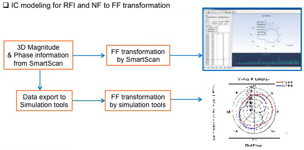
● NF to FF Transformation
● RFI Analysis
NF to FF Transformation
Mathematically, the ability to perform near field to far field transformation is not new (the first methodologies were developed in the 1950’s, with widespread application beginning in the 1980’s). This methodology is typically used for antenna characterization, but has been less frequently used for EMI prediction. With the available phase information, the maximized FF transformation from NF data showed an acceptable match to chamber measurements.
RFI Analysis
The objective of RFI prediction is to predict the coupling between noise sources (such as ICs, camera modules, flex cables, etc.) and wireless antennas. The prediction accuracy depends on how well the source models have been created. There are two types of sources: conducted sources and field coupled sources. Each type has its own advantages and disadvantages, and we believe the combination of scanned data for fields and voltage/current data from IBIS is the best modeling method. The phase information makes this combined approached possible. This way modules and ICs can be scanned, the obtained data can be used to predict RFI coupling within systems, and it can then be used to qualify ICs and modules to reduce the chance of RFI problems later in the product design.

Required Equipment
● SmartScan-PM
● Oscilloscope or VNA depending on frequency rangese
● EMI Probes
● Comb generator or other hardware for system calibration
Oscilloscope or VNA
An oscilloscope becomes quite expensive as the bandwidth increases. An oscilloscope can be used for any frequency range, but 4-6 GHz is the practical limit for obtaining phase information using an oscilloscope. VNA can be used for higher frequencies.